
TM 5-6675-348-13&P
(38) Disassemble female end of Operator
Cable (36).
NOTE
Hydraulic hoses for both sides of
130G Grader install the same. The
right side is shown.
Mark return line short hose before
installation.
For ease of installation, hold
hydraulic lines toward top of
130G Grader's Gooseneck while
installing. If hydraulic lines hit an
obstruction during installation, twist
and push lines at the same time.
Route straight end of hydraulic lines
through Gooseneck from front of
130G Grader to back.
Steps (40) through (45) require the aid of
an assistant.
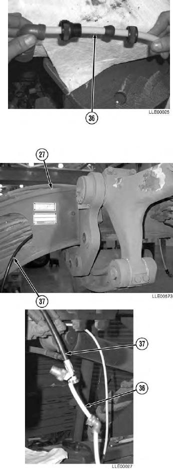
(39) Locate Load Sense Line (37).
(40) Push straight end of Load Sense Line (37)
through Gooseneck (27), starting from the
rear and pushing toward the front of the
Gooseneck (27).
(41) Cable tie female end of Operator Cable (36) to
Load Sense Line (37) on straight end of Load
Sense Line (37).
(42) With the aid of an assistant, pull Load Sense
Line (37) until female end of Operator
Cable (36) exits through rear side of
Gooseneck (27).
(43) Remove Load Sense Line (37).
3-93