
TM 5-6675-348-13&P
(83) Repeat Steps (46) through (81) for
right-side installation.
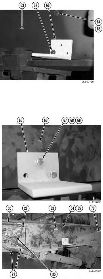
(84) Temporarily install right-side
Gooseneck Panel (63), six
washers (64), and six bolts (65).
(85) Temporarily install Mainfall Slope
Sensor Bracket (66) to right-side
Gooseneck Panel (63), using existing
bolt (67).
(86) Level, mark, and center punch
Mainfall Slope Sensor Bracket (66)
mounting holes.
(87) Remove bolt (67), Mainfall Slope
Sensor Bracket (66), six bolts (65), six
washers (64), and right-side Gooseneck
Panel (63).
(88) Drill two 1/2-in. (13 mm) holes at
punch marks.
(89) Align Mainfall Slope Sensor Bracket (66)
to bottom of right-side Gooseneck
Panel (63).
(90) Install with two bolts (67),
lockwashers (68), and nuts (69).
(91) Tighten nuts (69).
(92) Install both right-side Gooseneck
Panels (63) and (70) and Float
Valve (26) with eight washers (64) and
bolts (65).
(93) Install two Float Valve lines (35) to Float
Valve (26).
NOTE
Position Scarifier Hydraulic Lines
clockwise as far as possible to allow
clearance for the Remote Interface Box.
(94) Reposition Scarifier Hydraulic Lines (71)
clockwise as far as possible.
3-100