4 2 . Ge ne ra l
The tribrach assembly consists of the base
plate assembly, leveling screws, optical plumb-
ing assembly, circular level and tribrach. The
base plate provides a means for securing the
target set to the tripod. Leveling is accom-
plished by means of the leveling screws. Precise
location of the target set over the station point
is verified by sighting through the optical
plummet eyepiece.
4 3 . Ba se Pla t e Asse m bly
a. Removal and Disassembly.
(1) Remove the tribrach assembly from
the tripod and target set (para 27).
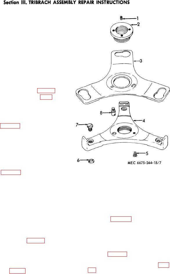
(2) Loosen the lock screw (8, fig. 7) and
push the spring plate (3) clockwise as
far as possible.
(3) Lift the base plate assembly from the
tribrach.
(4) Refer to figure 7 and disassemble the
base plate assembly.
b. Repair and Replacement. Remove burs and
straighten minor dents. Refinish and polish
scratched or scored bearing surfaces. Replace
parts damaged beyond repair with serviceable
parts.
c. Reassembly and Installation.
(1) Refer to figure 7 and reassemble the
base plate assembly.
(2) Position the base plate assembly on
5
Screw, guide
1
Setscrew
6
Nut
2
Nut
the tribrach making sure the feet of
3
Plate, spring
7
Bearing
the leveling screws engage the larger
8
Screw, lock
4
Plate, base
part of the slots in the spring plate
Figure 7. Base plate assembly, disassembly
(3).
and reassembly.
(3) Push the spring plate counterclock-
wise until it engages the leveling
(2) Refer to figure 8 and remove and
screw feet and tighten the lock screw
disassemble the leveling screw.
(8).
b. Repair. Straighten out minor bends and
(4) Install the tribrach assembly on the
dents. File smooth all burs. Replace parts dam-
tripod and target set (para 27).
aged beyond repair with serviceable parts.
c. Reassembly and Installation.
4 4 . Le ve ling Sc re w s
(1) Refer to figure 8 and reassemble and
a. Removal and Disassembly.
install the leveling screw.
(2) Install the loose plate assembly (para
(1) Remove the base plate assembly from
the tribrach (para 43).
AGO 10139A

