
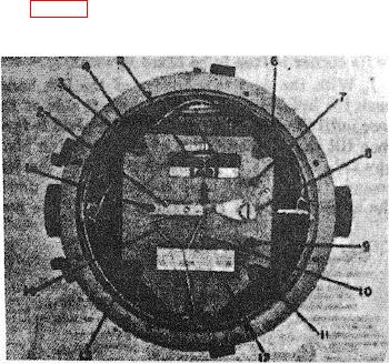
c. Remove the four screws (8, fig. 13) which hold the mounting plate to the rubber shock mount brackets (4, 6,
11, and 18).
1
Post
8
Adjusting
2
Top bearing plate
9
Post
3
Screw
10
Actuating rod
4
Mounting bracket
11
Mounting bracket
6
Pressure sensing ele-
12
Mounting plate
ment
18
Mounting bracket
6
Mounting bracket
14
Rack of support
7
Post
bracket assembly
Figure 13. Removal of mechanism assembly.
d. With the case positioned so that the two posts (7 and 9) are to the right, grasp the posts between the thumb
and forefinger of the right hand so that the mechanism will not drop into the case. These two posts are all that should be
held in removing the mechanism from the case.
41