
TM 5-6665-202-13
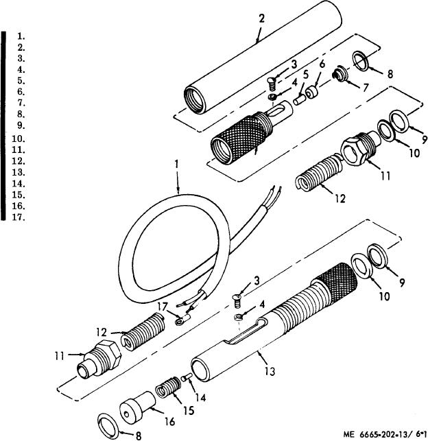
Cable assembly
Battery case
Screw
Lockwasher
Contact
Bushing
Spring
Packing, preformed
Washer
Packing, preformed
Bushing
Spring
Adapter
Contact
Spring
Bushing
Terminal clip
Figure 6-1. Battery adapter, disassembly and reassembly.
(2) Cleaning, inspection, and repair.
e. Chassis.
(1) Removal.
(a) Wipe the capacitor with a clean, dry
(a) Remove the capacitor (subpara d).
cloth.
(b) Remove the terminal board (subpara
(b) Inspect for breaks, corrosion, or
c).
other damaged connections.
(c) Remove the header (subpara b).
(c) Replace a defective capacitor as nec-
(2) Cleaning, inspection and repair.
essary.
(a) Wipe the chassis with a clean, dry
(3) Testing the capacitor. Test the capaci-
cloth.
tor with a suitable capacitor tester. The capaci-
(b) Inspect for breaks, cracks, bends,
tance should be 1.43 microfarad at 100 VDC.
corrosion, damaged threaded areas, and other de-
fects.
(4) Installation. Reverse removal proce-
dure and install the capacitor in the transmitter
(c) Replace a d a m a g e d or defective
and receiver assembly.
chassis as necessary.
Change 1