TM 10-4510-206-14
TO 40P1-6-2-1
5 - 7.
REPAIR PROCEDURES (CONT'D)
p. Master Control Box Assembly (Cont'd)
3. Inspect components and wires for burns and breaks and replace any
component or wire found defective .
4. Using multimeter,
c h e c k c o n t i n u i t y f r o m f r o n t o f p l u g ( 5 ) to
output on each pin.
Replace connector (steps 12 and 13) if test
f a i l s o n a n y p i n.
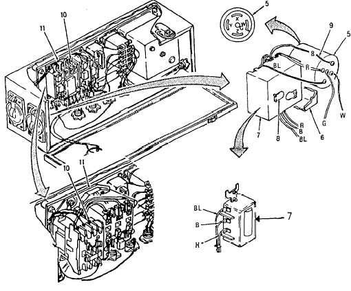
5. On Model PBU-100, before serial number PBU100442, pull off cover
(6) and inspect overload heaters (8) for damage. Replace (steps
1 5 a n d 1 6 ) i f d e f e c t i v e .
6. On Model PBU-100,
t o t e s t l o a d l i m i t s w i t c h ( 7 ) , c h e c k c o n t i n u i ty
f r o m w i r e t e r m i n a l s ( 9 ) o n b a c k o f p l u g ( 5 ) t o t e r m i n a l s ( 1 0 ) at
m o t o r c o n t a c t o r ( 1 1 ) . With switch (7) turned off, meter reads open
c i r c u i t .
W i t h s w i t c h ( 7 ) t u r n e d o n,
m e t e r r e a d s c o n t i n u i t y on
e a c h l i k e c o l o r e d w i r e . R e p l a c e s w i t c h ( 7 ) ( s t e p s 1 7 a n d 1 8 ) if
c o n t i n u i t y t e s t f a i l s .
On Model PBU-100, before
serial number PBU100442
BL- BLUE
G- GREEN
B-
BLACK
R-
RED
W-
WHITE
On Model PBU-100, serial
numbers PBU100442 and
subsequent and Model HEI-100
C h a n g e 7 5 - 8 9