TM 10-4510-206-14
TO 40P1-6-2-1
5 - 7.
REPAIR PROCEDURES (CONT'D)
a .
Power Cable Assembly.
On Model PBU-100, before serial number PBU100442 and on Model HEI-
100,
the power assembly cables are terminated by male and female
c o n n e c t o r s a n d a n e l e c t r o l e t b o x ( T - j u n c t i o n ).
The procedures for
r e p a i r i n g t h e m a l e a n d f e m a l e c o n n e c t o r s a r e t h e s a m e.
The
p r o c e d u r e f o r r e p a i r i n g a T - j u n c t i o n i s d i f f e r e n t f r o m r e p a i r
procedures of the male and female connectors.
Before attempting
r e p a i r , d e t e r m i n e w h i c h l e g o f t h e c a b l e a s s e m b l y i s d e f e c t i v e,
a n d i f p o s s i b l e,
w h i c h w i r e i s d e f e c t i v e b y i n s p e c t i o n o r
c o n t i n u i t y c h e c k s.
On Model PBU-100,
serial numbers PBU100442 and subsequent have
power cables with a molded T-junction.
T h e r e f o r e,
t h e o n l y r e p a ir
t o t h e c a b l e i s r e p l a c e m e n t o f e n d p l u g s ( s t e p s l - 9 b e l o w ) .
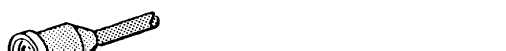
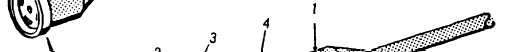
1 . P e e l b a c k c a p c o v e r ( 1 ) f r o m c o n n e c t o r ( 2 ).
2. Inspect cable wires and connector for defects .
3.Remove connector by unscrewing five terminal screws (3).
4 . R e m o v e c a p c o v e r ( 1 ) f r o m c a b l e ( 4 ).
5 - 6 C h a n g e 7